Saturday 30 March 2013

Sole Beams & Bulkhead

Making reasonably progress on my Somes Sound - having gained some inspiration from fellow builders.

First I needed to fit the trunk sole beam which slants downhill towards the stern.  This necessitated removing some material from the underside of the aft end of the beam to ft against the trunk cleat.  Confusing isn't it?  I thought so, but now having built it, all seems crystal clear.  That's one of many enjoyment factors I derive from this project - staring into a sea of mist and navigating to the destination...so to speak..

 I fitted out the sole beams which sit on top of the floors and are attached to the trunk by a "beveled mortice" joint - not one I had heard of before but I assume that this was what the designer specified.

 The beams are made from Douglas Fir and dimensioned to the same thickness of the floors.  I enjoyed this process safe in the knowledge that any mistakes would be out of sight beneath the sole....as it transpired most of the joints were reasonably tight.

Getting the sole beams to fit to the floors was a little slower as I needed to pick up the curve and camber of the floors for each of the beams - 5 aside.  I relied upon a torpedo spirit level to gauge where the beams should be attached to the floors and then did a final test by running a straight edge across the span of the beams ensuring that they were level with each other.  So far so good.

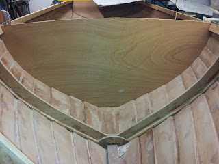
Completed sole beams attached to trunk sole beam and floors
I decided not to screw the beams where they are morticed to the trunk sole beam relying upon a clamp to hold the bevel mortised joint secure, once I had a screw in the outer end of the beam where it meets the floor.  Having reviewed it today when the epoxy had cured, it seems like a good solution.

I debated about whether to add the V notch into the bulkhead to create a paneling effect.  So I bit the bullet and cut the notches using a V shaped cutter in a small router, which did a fine job.  I'm glad I did as I think it looks quite good.  Getting the bulkhead square and vertical to the waterline, required some more fine tuning, but I think it is a good fit now and ready for gluing to the hull.


Paneling effect looks quite authentic and adds relief to a large flat surface.  Cut with a V shaped router.  The grooves are in fact equidistant - the photo was taken from an angle which suggests otherwise.


The bulkhead itself seemed to be slightly warped so I had to clamp a straight board across the top of it to make sure everything was lined up correctly.  The bulkhead is positioned vertical to the waterline so I relied upon a long spirit level to ensure it was.

Next I have to glue and fit the cleats to the for'ard of the bulkhead and refine the shape of the camber on top of the bulkhead.  

Monday 25 March 2013

Floors Glue Up & shaping sheer clamp

One small sentence in the instructions couldn't take three days...could it?!!  But yep, gluing in the floors is quite time consuming so by the time I had refined their fitting and drilled for the screws, it was quite a slow procedure.
Each screw needed three separate drill bits to make the pilot holes, 12mm for the counter sunk portion, 6mm for the clearance and 4mm for the pilot in the keelson  - previous short cuts resulted in broken screws, swear word and general self flagellation.....


Here you can see the floors being epoxied to the hull.  A large screw secures it at the trunk down into the keelson, while further smaller screws are driven up from outside the hull at the plank laps
into the floors.  The "fillers" are screwed into the keelson acting as spacer between the floors.  On top of this sandwich a truck cleat is secured, which makes for a tight integrated structure allowing the lead keels weight to be distributed over the hull and tying in the centre board trunk structure.


Here you can see the fillers screwed and glued into between the floors before the trunk log cleat is assembled on top.  I made wood plug to fill the screw holes, which were chiseled flush before attaching the trunk log cleat.


The finished result cooking under the infrared panel to counter the unseasonable arctic weather we are experiencing.  


Meanwhile, I made up a camber template to shape the sheers and the top of the bulkhead.  The camber is specified as a 2" rise over 6'.  

 This defines the shape of the side decks and I assume will impact also on the angle of the coaming.  It looks like in my exuberance to plane the sheers, I may have over flattened the starboard sheer-clamp near stations 12 and 14, so I may have to glue back in some filler wood and re-plane before fitting the side deck...should matter as no one will ever know..unless they read it here!

I found it a good idea to mark the topside of the template as it is easy to have it the wrong side up....which might have been the reason for my flattened sheer-clamp!!


Thursday 21 March 2013

Bulkhead Dryfitted

Today I managed to get the bulkhead dry fitted and also refine the camber of the sheer clamps.  

Following my earlier post, I contacted John Brooks, Somes Sound 12.5 designer, who quickly reassured me that the bulkhead would be fine without having to make a new web frame also.  Fitting the bulkhead was quite slow, because I fitted the bulkhead in one piece rather than in two halves: the narrowing of the planks as you move forward creates a challenge since you have to insert the bulkhead aft of its final position where the jogs do not line up....


The specifications for shaping the sheer clamp camber call for a pattern to be made which has a rise of 2" over 6'.  This also defines the shape for the top of the bulk head in addition to the cambers of sheer clamps.  It does however cause the camber at the stem to look quite flat, but I am sure when the deck is fitted it will make sense visually.


Play came to a stop early today while cutting the cleats to support the bulkhead, my nice shiny Japanese pull saw ripped through my thumb...ouch!!


A salutary reminder to stay awake and keep flesh and tools apart......

Tuesday 19 March 2013

Sheer clamps, Floors and Moving Stations!


The cold weather has slowed progress which is why it's been a while since I have updated the blog.  I purchased a Far InfraRed panel which I suspended over the boat - this is an efficient way of getting the wood up to temperature for epoxy gluing.
Far Infra Red Heating Panel
Since the last post I have installed the sheer clamps.  The instructions suggest making it out of 2 laminations, but I had a few break while bending, so I opted to use 3 laminations.  That made the process slower as I had to glue up each lamination separately and wait a day in between, which was effectively 6 elapsed days.  The sheer clamps however fitted snugly and look robust.

The next phase was to install the floors either side of the trunk.  This proved quite tedious as hopping in and out of the boat slows down progress considerably - so I was delighted when our neighbour's son Eoin volunteered to help.  We have managed to get the floors dry fitted and screwed to the hull and also the spacers and log cleat which ties the whole assembly together.  Despite making the laminated floors over the hull before planking, they still needed refining and scribing to get an exact fit.
 While examining the plans and ensuring that we had marked out the positions for the keel bolts, I became suspicious of some dimensions for station #6.  It seems that I made a rookie mistake of assuming that all stations were 24" apart when I set up my jig and molds.  In fact, all except station # 6 are 24" apart, while 6 is 20" aft of station 4, which meant that my forward bulk head would have been too far aft.


So after sleeping on the problem I decided to take out the #6 web frame.  This is where once again the Bosch Multi tool saved my bacon and allowed me to cut effortlessly through the joints without damaging the hull planks whatsoever.  It really is a remarkable tool...
Hull cleaned up after frame removal

I managed to get the old frame out of the hull intact and thought that I may be able to re-use it by marking it against the new template  made, but the hull narrows by some 1 1/4" so it wasn't a runner.  However I don't believe there is any need to remake a frame as the bulkhead with some cleats will be more than strong enough on its own, the frame's purpose no longer really required, as it was initially for shaping the hull while planking. (need to check with my friendly designer John Brooks)

Template used to measure Bulkhead at new position

I made a template and used small lengths of 1/4" ply hot glued to it to copy the inside shape of the hull faithfully.  It was a slow process, but gave me an accurate shape in the end.  I will now cut the bulkhead out from 1/2" material, so by the next post you should see it fitted.

Here you can see the hull where the old station has been removed - this is before I dressed the planks with a light sanding which removed all blemishes.  Can't speak highly enough of this Bosch Multi Tool.

It looks like I will get off lightly with this mistake as I didn't take any other references from station 6, except for the hull is now about 1 1/4" narrower at this point.  The lines of the hull look great so I am hoping that this slight modification will only ensure greater streamlining and a faster hull!!

This shot was taken just to re-emphasize the Houdini like cramped working conditions:-